Liquid Cooling Infrastructure Inspection and Leak Detection Automation
Automated sensors across the cooling loop catch leaks before they destroy hardware.
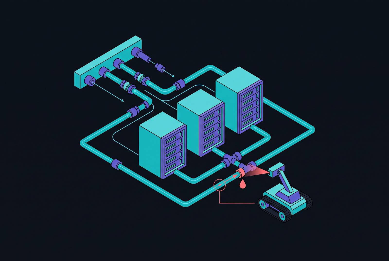
Liquid cooling has moved from a specialty accommodation for a handful of extreme-density racks to a mainstream infrastructure decision. A Data Center World survey found 19% of respondents already running liquid cooling in production, with more deployments planned in the near term, and the market backing that shift is expanding fast: liquid cooling was valued at USD 4.8 billion in 2025 and is projected to reach USD 27.1 billion by 2035, growing at an 18.2% compound annual rate. None of that growth matters much if the leak detection built around it stays stuck in the age of drip pans and hourly walkthroughs. Reliable automated inspection depends on stacking several sensor types and monitoring layers across the entire loop, from the CDU down to the cold plate at the chip, because no single technology catches everything that can go wrong.
The pressure behind this shift is not cosmetic. AI workloads are expected to climb from 15% to 40% of data center workloads by 2030, and the racks running them are outgrowing what air can cool. A traditional rack pulled 10 to 15 kW; a modern AI rack can hit 100 kW or more. That is not an incremental jump but a different physical regime, and it explains why liquid has moved into the thermal path even though operators have to accept the added complexity.
Liquid cooling failure modes and why they demand layered detection
Air and hardware barely touch in a conventional row. A failed fan just lets heat build, and the management system flags rising temperatures well before anything on the board is at risk. That grace period does not exist once liquid enters the equation.
A leak in a liquid-cooled system can short a board immediately, start corroding PCB traces on contact, or set off a slower oxidation process that only shows up as failures months down the line. Three very different timelines, three very different damage signatures, all from the same root event: fluid where fluid should not be.
The stakes of getting this wrong are not theoretical. A cooling system failure at a Google facility in Paris flooded infrastructure and started fires that disrupted services across the continent, an illustration of reactive tools, containment trays, moisture sensors, threshold alarms, doing what they're built to do: respond after the damage has already started. Such incidents are not freak one-offs but evidence that the vulnerability is at the industry level, not the operator level.
The response-time gap that makes passive and visual methods inadequate
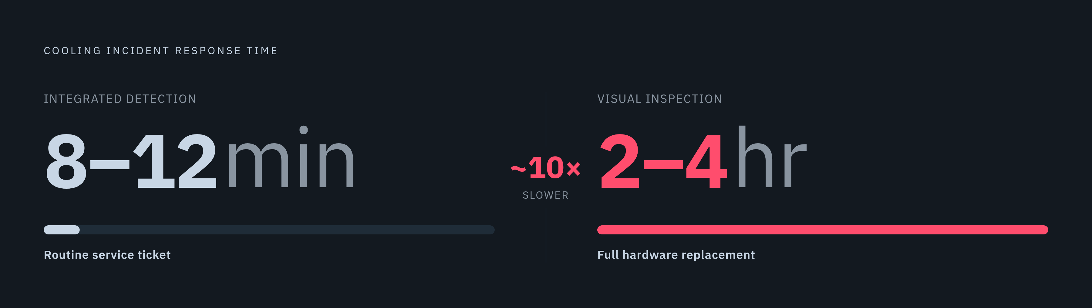
The numbers on response time make the case better than any anecdote could. Facilities running integrated detection systems respond to cooling incidents in 8 to 12 minutes on average. Facilities that still lean on visual inspection average 2 to 4 hours. That's not a marginal gap, it's close to an order of magnitude, and with liquid damage, that gap often separates a routine service ticket from a full hardware replacement.
Passive tools, containment trays, static moisture sensors, threshold alarms, share one structural flaw: they only trigger once fluid has physically reached the sensor. By definition, the leak has already happened by the time anyone gets a signal.
Manual walkthroughs carry a second, quieter problem on top of that. A technician logging readings while walking the floor, or climbing to inspect overhead manifolds, is generating data that might not reach the CMMS for hours, sometimes days. By the time that reading is entered into a system anyone can act on, the window where intervention would have mattered has already closed.
Sensing the full cooling loop: how cable, point, and optical sensors divide the coverage problem
No single sensor covers every place a leak can start or every fluid that might be doing the leaking. The logic here is spatial and physical: it is about covering every place a leak can start and every fluid that might be doing the leaking, not merely stacking redundant hardware for its own sake.
Cable-based, or linear, sensors run continuously along pipe routes, under raised floors, and around facility perimeters. In a hyperscale facility where sending someone to physically check every meter of pipe is not realistic, this is the only coverage method that scales. These sensors are built for conductive liquids like water and glycol solutions, and they detect a leak anywhere along the length of the cable rather than at one fixed point. Icon Process Controls' LDC Series is one example of a leak detection cable designed for exactly this job, and the natural fit is long chilled water lines, CDU supply and return runs, and overhead manifold paths.
Point, or spot, sensors work the opposite way: fixed locations at known risk spots, drip pans, pump housings, quick-connect fittings, cold plate manifolds, where even a small puddle means something has already gone wrong. They catch small leaks fast, before they spread, and they cover components that cable routing physically can't wrap around. Rope-based devices extend that idea around an entire cabinet perimeter or up a vertical pipe run, and running spot and rope sensors together, rather than choosing one over the other, is a common approach.
Then there's the fluid type itself. Immersion cooling and some specialty direct-to-chip systems use dielectric fluids that don't conduct electricity. Conductive cable and point sensors have nothing to detect, there's no electrical path for them to complete. Optical, or light-based, sensors close that gap by detecting the physical presence of liquid without needing conductivity. That capability is becoming more relevant by the year: the coolant-specific detection segment tied to immersion and direct-to-chip systems is growing at 11.8% CAGR, faster than the leak detection market overall, as dielectric fluid use continues to expand.
Coolant chemistry monitoring: the upstream signal that precedes physical leaks
A lot of operators treat coolant the way they'd treat coolant in a car: fill it, check the concentration once, move on. That assumption doesn't hold in a closed loop running continuously under heat and pressure. Left unmanaged, coolant chemistry doesn't stay stable, it drifts, and it drifts toward exactly the conditions that cause corrosion and thermal breakdown.
Propylene glycol oxidizes when it's exposed to oxygen, heat, and metallic catalysts, which is a fair description of what's happening inside a CDU and cold plate loop at any given moment. The oxidation byproducts are organic acids, and those acids eat into the alkalinity reserve and drag pH downward over time.
Once pH drops below 7.0, ferrous metal starts to rust, and non-ferrous metals like the copper, brass, and aluminum used in cold plates, manifolds, and brazed joints corrode aggressively. That means the leak conditions are forming from inside the metal outward, long before anyone sees a drop of fluid on the floor. Tracking pH, conductivity, flow rate, pressure, and temperature together gives a real picture of coolant health, enabling predictive maintenance instead of waiting for something to fail before reacting.
What AI-assisted forecasting adds and cannot do
Sunkara and Konakanchi published a proof-of-concept IoT monitoring system that pairs LSTM neural networks for probabilistic leak forecasting with Random Forest classifiers for catching events in real time. Tested against synthetic data built to align with ASHRAE 2021 standards, the system hit 96.5% detection accuracy and 87% forecasting accuracy at 90% probability, within a plus-or-minus 30-minute window.
The architecture behind it uses MQTT for streaming, InfluxDB for storage, and Streamlit dashboards for visualization, and the practical payoff is a system that can forecast a leak 2 to 4 hours before it happens while still flagging sudden events within a minute of onset.
One finding from that work deserves particular attention: humidity, pressure, and flow rate turned out to be the strongest predictive signals, while temperature barely moved in the early stages, a result of thermal inertia in server hardware that keeps temperature readings stable even as trouble is already building. An operator watching temperature alone will miss the early warning entirely, because by the time temperature responds, the precursors have already passed.
Forecasting like this narrows the window operators have to act. It does not replace the physical sensing layer described above, it depends on it, since a model is only as good as the pressure, flow, and humidity data feeding it.
Integrating detection outputs into BMS and DCIM so automated response happens
None of this sensing matters unless it triggers something. A cable sensor that reports a leak to a local alarm panel no one is watching in real time offers little advantage over a technician's flashlight. The value appears when detection output feeds directly into the Building Management System or a DCIM platform, where it can trigger action rather than just a notification.
Integrated properly, that connection lets the system close solenoid valves feeding the affected loop segment automatically, stopping the leak's spread before a human has even confirmed there's a problem. It can also ramp down IT load on the affected rack through server management interfaces, cutting heat output if cooling capacity is compromised, and shut down HVAC equipment nearby so it doesn't spread moisture further, adjusting ventilation to help the area dry out. These actions happen within seconds of detection, and that speed is the entire point: the value isn't in alerting a person faster, it's in acting before a person is even in position to respond.
Getting there depends on the integration protocol tying the leak detection panel to the BMS. Standards like BACnet, SNMP, and vendor APIs determine whether detection data actually reaches the NOC's existing monitoring dashboards and building automation systems, or just sits isolated on its own panel.
Wireless mesh network architecture adds one more layer of resilience to the whole setup: sensors talk to each other across multiple paths, and if one node goes down, the network reroutes around it automatically. Monitoring continuity holds even when part of the system is offline, which matters most in exactly the moment when something has already gone wrong elsewhere in the facility.
Sources
- Smart IoT-Based Leak Forecasting and Detection for Energy-Efficient Liquid Cooling in AI Data Centers
- AI Data Center Cooling: Liquid Cooling Systems, Instrumentation, and Leak Detection
- Data Center Leak Detection: Protecting Critical Infrastructure from Costly Downtime
- iconprocon.com
- 12 Ways a Data Center Glycol Loop Goes Wrong
- iconprocon.com
- dober.com
- rightpowerups.com.my